Our country pages
Europe
Search
How to remove Radon from the foundations of a building
Radon Resisting Membranes
To ensure a necessary degree of separation in the ground floor so that interior building spaces are not affected by heat losses if a radon soil gas control system is ever activated, a radon, air and moisture protection system should always be installed by competent personnel.
Existing Buildings
Prior to installing an activated radon soil gas control system it must be established that there is sufficient separation between the sub-floor construction and interior spaces and superstructure construction cavities.
Keep in mind that, depending on age, an existing building may or may not have either a radon soil gas or a damp resisting membrane.
Jump to section
Establish An External Position For The Easi-Sump Cap-Link
Establish An External Position For The Easi-Sump Cap-Link
The following constraints would apply when a Radon Soil Gas Control System is activated:
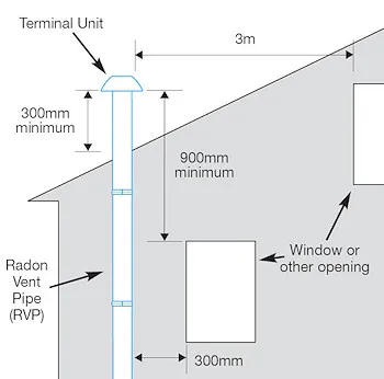
- There should be no openings into a building, e.g. windows, vents, or vertical control joints, less than 300mm from any part of the RVP.
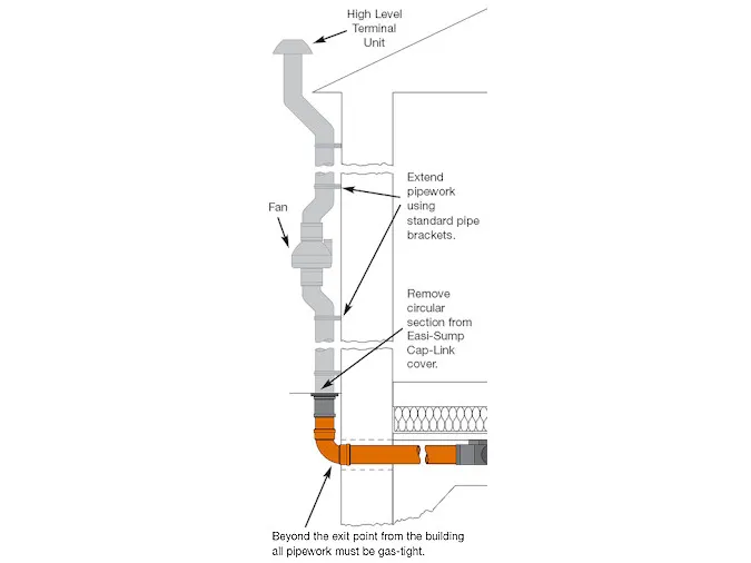
- The terminal unit of the radon vent pipe should be positioned at least 300mm above the surface of the roof and 900mm above any window or other opening into the building. It should be located at least 3m away from any window or opening that is less than 900mm below the terminal unit (see diagram below).
- All exposed and visible vertical RVP’s should be clearly identified for what they are - A Radon Soil Gas Control System.
Install The Easi-Sump Radon Sump At Sub-Floor Level
Install The Easi-Sump Radon Sump At Sub-Floor Level
The hardcore layer in the floor construction of a building should be clean, dry, well-compacted, and gas permeable (following the compaction process), i.e. suitable material (preferably of single size) should be used which is greater than 10mm and less than 50mm, with no fines (or to an equivalent specification which results in adequate permeability following compaction).
The Easi-Sump radon sump is placed within this hardcore layer
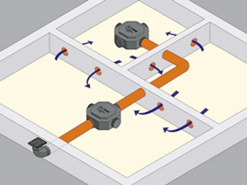
Each Easi-Sump radon sump should be placed centrally in an area of hardcore. In buildings where there may be many foundation compartments, a short length of 110mm diameter pipe (or a gap of similar size) should be inserted in all internal foundation rising walls, at centres not exceeding 1m and at approximately the same level as the Easi-Sump. This will ensure that the permeability of the hardcore layer remains effective throughout the extent of the building’s foundations.
In the event that a sub-floor radon soil gas control system is activated, it is important that heat producing appliances and the patterns of natural ventilation in interior building spaces should not be affected, or that heat losses be increased. To ensure a necessary degree of separation in the construction of a ground floor, a Radon Resisting Membrane should always be installed by competent personnel.
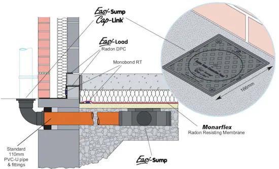
The Easi-Sump has four spigots, intended for the insertion of 110mm diameter drainage pipes (see drawing to right). Typically, one of these pipes should be laid, in accordance with standard drainage pipe installation procedures, to connect with the Easi-Sump Cap-Link, which is located just outside the external wall of the building. The other blanked-off spigots should be opened, as required, to accept pipe inserts coming from another part of the building’s foundation, and/or another Easi-Sump. For reasons of condensation control, falls in pipework should be towards the Easi-Sump.
Depending on the quality of ground floor specification, whether or not it is accurately followed on site, the quality of workmanship, and level of technical control during this critical phase of construction, the effective pressure field of the Easi-Sump radon sump may extend well beyond an area of 250m², or fall below 50m².
As a general rule:
- with Category A Construction Execution, allow for one Easi-Sump to service an area not greater than 200m²;
- with Category B Construction Execution, allow for one Easi-Sump to service an area not greater than 100m²;
- with Category C Construction Execution, allow for one Easi-Sump to service an area not greater than 50m².
Extra Easi-Sumps may be added, or interlinked, to a subfloor network in order to service larger areas.
Seal The Radon Sump Opening Through The External Wall Of The Building
Seal The Radon Sump Opening Through The External Wall Of The Building
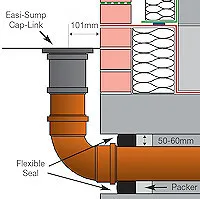
Before connecting the Easi-Sump radon sump to an Easi-Sump Cap-Link, however, a 110mm pipe exiting a building must be installed in a masonry opening which should:
- Be of sufficient size – to accommodate any reasonable construction settlement during the building’s lifecycle which might interfere with the pipe;
- Have adequate structural support above the opening – in order to prevent any damage being caused to the pipe from masonry loading overhead;
- Have an approved flexible seal between the pipe and masonry – in order to avoid the possibility of drawing in air from the exterior thereby reducing the effectiveness of an activated radon soil gas control system. Provide 50mm to 60mm clearance around the pipe to allow for sealing.
Beyond this exit point from the building, all pipework must be gastight.
Final Connection to the Easi-Sump Cap-Link
Final Connection to the Easi-Sump Cap-Link
To complete the installation fit the externally located Easi-Sump Cap-Link to the 110mm PVC-U pipe leading to the sub-floor Easi-Sump radon sump. This pipe should be cut to finish flush with the finished surface of the external wall.
The 101mm recommended dimension, (see drawings above), between the external face of the wall and the central drill location mark on the Easi-Sump Cap-Link cover, facilitates the use of standard pipe fitting for a Radon Vent Pipe (RVP) if one is required at a later date.
The cover of the Easi-Sump Cap-Link is supplied already in position, with stainless steel screws pre-fixed. This is to prevent:
- Tampering and/or unauthorised interference;
- Rain penetration and/or vermin entry into the subfloor network of the building.
There is no need to open these screws when installing the Easi-Sump Cap-Link.
When a Radon Soil Gas Control System is being activated, a circular section of the cover is removed to install a Radon Vent Pipe. This section is of sufficient size to accept a 110mm PVC-U pipe, with a small clearance all around. A central drill locator mark in the cover facilitates removal on site.
